ESP32 Modules and Boards
Espressif designed and manufactured several development modules and boards to help users evaluate functionality of the ESP32 family of chips. Development boards, depending on intended functionality, have exposed GPIO pins headers, provide USB programming interface, JTAG interface as well as peripherals like touch pads, LCD screen, SD card slot, camera module header, etc.
For details please refer to documentation below, provided together with description of particular boards.
Note
This section describes the latest versions of boards. Previous versions of boards, including these not produced anymore, are described in section Previous Versions of ESP32 Modules and Boards.
WROOM and WROVER Modules
A family of small modules that contain ESP32 chip on board together with some key components including a crystal oscillator and an antenna matching circuit. This makes it easier to provide an ESP32 based solution ready to integrate into final products. Such modules can be also used for evaluation after adding a few extra components like a programming interface, bootstrapping resistors and break out headers. The key characteristics of these modules are summarized in the following table. Some additional details are covered in the following chapters.
| – | Key Components | Dimensions [mm] | |||||
|---|---|---|---|---|---|---|---|
| Module | Chip | Flash | RAM | Ant. | L | W | D |
| ESP-WROOM-32 | ESP32-D0WDQ6 | 4MB | – | MIFA | 25.5 | 18 | 3.1 |
| ESP-WROOM-32D | ESP32-D0WD | 4MB | – | MIFA | 25.5 | 18 | 3.1 |
| ESP32-WROOM-32U | ESP32-D0WD | 4MB | – | U.FL | 19.2 | 18 | 3.2 |
| ESP32-WROVER | ESP32-D0WDQ6 | 4MB | 4MB | MIFA | 31.4 | 18 | 3.2 |
| ESP32-WROVER-I | ESP32-D0WDQ6 | 4MB | 4MB | U.FL | 31.4 | 18 | 3.5 |
- MIFA - Meandered Inverted-F Antenna
- U.FL - U.FL / IPEX antenna connector
- ESP32 Chip Datasheet (PDF)
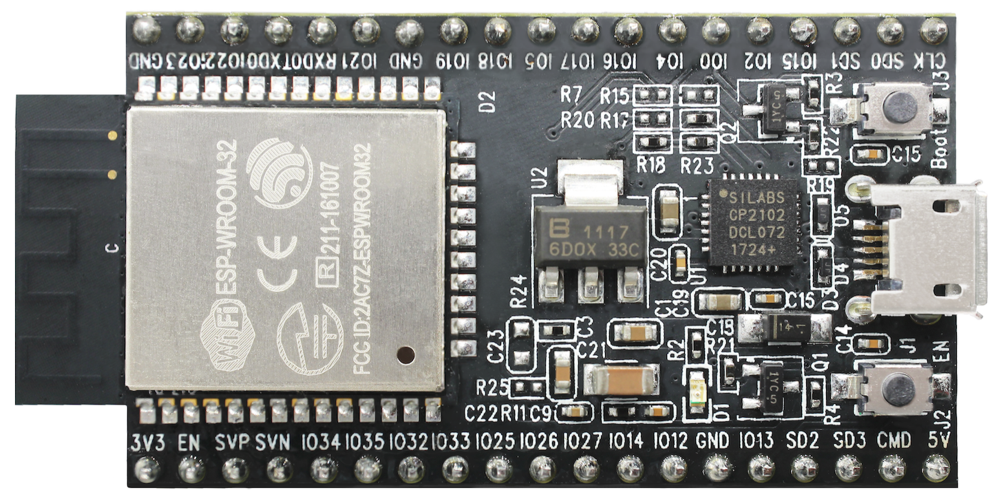
ESP-WROOM-32
A basic and commonly adopted ESP32 module with ESP32-D0WDQ6 chip on board. The first one of the WROOM / WROVER family released to the market.
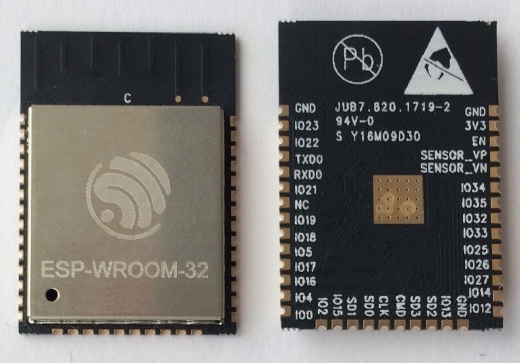
ESP-WROOM-32 module (front and back)
Documentation
- ESP-WROOM-32 Schematic (PDF)
- ESP-WROOM-32 Datasheet (PDF)
- ESP32 Module Reference Design (ZIP) containing OrCAD schematic, PCB layout, gerbers and BOM
ESP-WROOM-32D / ESP32-WROOM-32U
Both modules have ESP32-D0WD chip on board of a smaller footprint than ESP32-D0WDQ6 installed in ESP-WROOM-32. Version “D” has a MIFA antenna. Version “U” has just an U.FL / IPEX antenna connector. That makes it 6.3 mm shorter comparing to “D”, and also the smallest representative of the whole WROOM / WROVER family of modules.
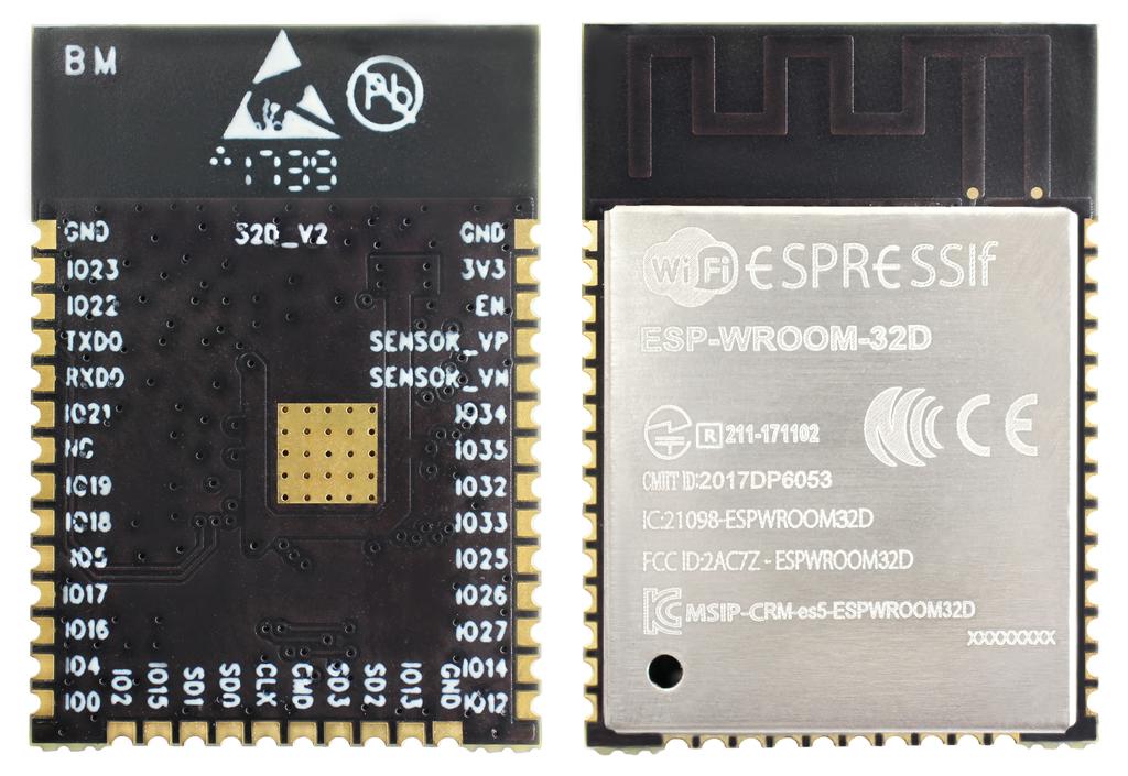
ESP-WROOM-32D module (back and front)
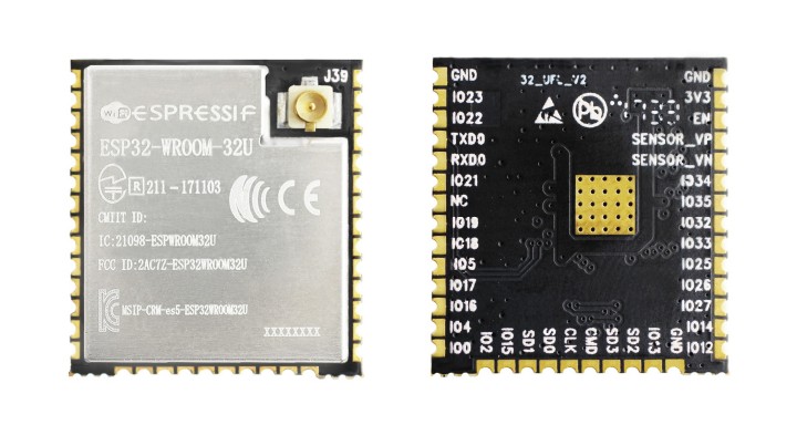
ESP32-WROOM-32U module (back and front)
Documentation
ESP32-WROVER
A step upgrade of ESP-WROOM-32 with an additional 4 MB SPI PSRAM (Pseudo static RAM). This module is provided in two versions: ‘ESP32-WROVER’ with PCB antenna (shown below) and ‘ESP32-WROVER-I’ with an U.FL / IPEX antenna connector. Because of additional components inside, this module is 5.9 mm longer than ESP-WROOM-32.
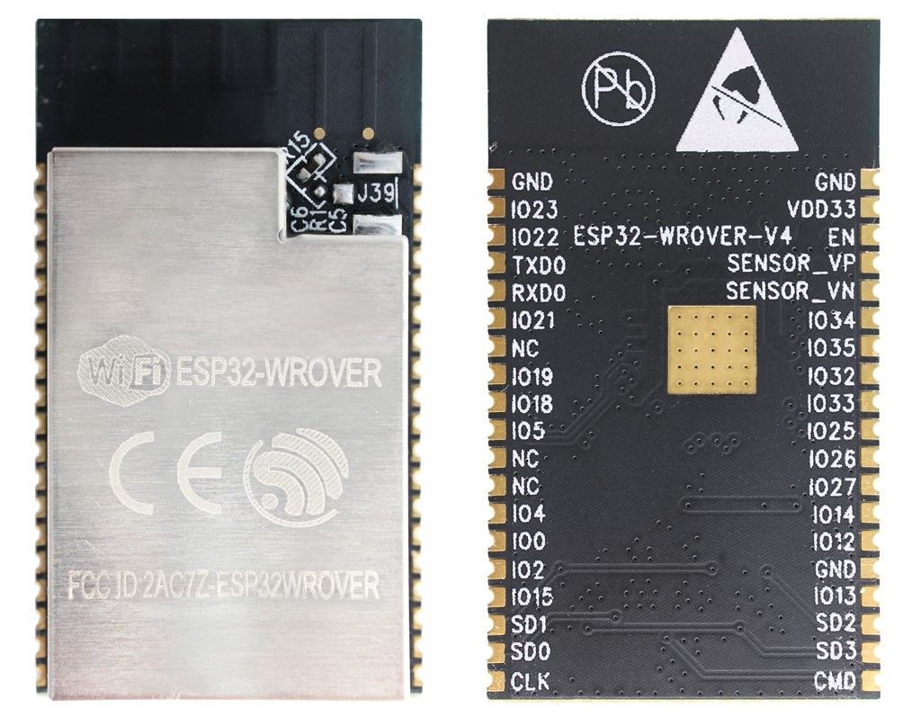
ESP32-WROVER module (front and back)
Documentation
- ESP32-WROVER Datasheet (PDF)
- ESP-PSRAM32 Datasheet (PDF)
ESP32-PICO-KIT V4
The smallest ESP32 development board with all the components required to connect it directly to a PC USB port, and pin headers to plug into a mini breadboard. It is equipped with ESP32-PICO-D4 chip that integrates 4MB flash memory, a crystal oscillator, filter capacitors and RF matching circuit in one single package. As result the fully functional development board requires only a few external components that can easy fit on a 20 x 52 mm PCB including antenna, LDO, USB-UART bridge and two buttons to reset it and put into download mode.
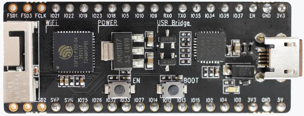
ESP32-PICO-KIT V4 board
Comparing to ESP32-PICO-KIT V3, this version has revised printout and reduced number of exposed pins. Instead of 20, only 17 header pins are populated, so V4 can fit into a mini breadboard.
Documentation
Previous Versions
ESP32 Core Board V2 / ESP32 DevKitC
Small and convenient development board with ESP-WROOM-32 module installed, break out pin headers and minimum additional components. Includes USB to serial programming interface, that also provides power supply for the board. Has pushbuttons to reset the board and put it in upload mode.
ESP32 Core Board V2 / ESP32 DevKitC board
Documentation
- ESP32-DevKitC Getting Started Guide
- ESP32 DevKitC Schematic (PDF)
- ESP32 Development Board Reference Design (ZIP) containing OrCAD schematic, PCB layout, gerbers and BOM
- CP210x USB to UART Bridge VCP Drivers
ESP-WROVER-KIT V3
The ESP-WROVER-KIT V3 development board has dual port USB to serial converter for programming and JTAG interface for debugging. Power supply is provided by USB interface or from standard 5 mm power supply jack. Power supply selection is done with a jumper and may be put on/off with a separate switch. This board has MicroSD card slot, 3.2” SPI LCD screen and dedicated header to connect a camera. It provides RGB diode for diagnostics. Includes 32.768 kHz XTAL for internal RTC to operate it in low power modes.
As all previous version of ESP-WROVER-KIT boards, it is ready to accommodate an ESP-WROOM-32 or ESP32-WROVER module.
This is the first release of ESP-WROVER-KIT shipped with ESP32-WROVER module installed by default. This release also introduced several design changes to conditioning and interlocking of signals to the bootstrapping pins. Also, a zero Ohm resistor (R166) has been added between WROVER/WROOM module and VDD33 net, which can be desoldered, or replaced with a shunt resistor, for current measurement. This is intended to facilitate power consumption analysis in various operation modes of ESP32. Refer to schematic - the changes are enclosed in green border.
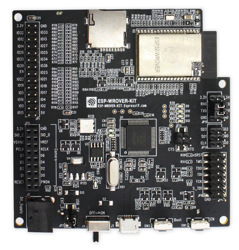
ESP-WROVER-KIT V3 board
The camera header has been changed from male back to female. The board soldermask is matte black. The board on picture above has ESP32-WROVER is installed.